|
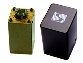
Silk
Interstage
|

|
|
Interstage
Test report
We
set up the test for frequency response, THD and FFT analysis under actual
working condition of the Interstage transformer; that's running with DC
unbalance and driven by 6V6(triode connected) tube. The result derived
from the output stage of SE300B with our new SILK S-325 output transformer.
List
of test equipment Our test drive circuit is based on 6SN7 (SRPP) input, C-coupling to 6V6 (triode connected) Interstage coupling that runs at +250V at 28mA. Output tube SE300B is running at +350V at 78mA.
|
|
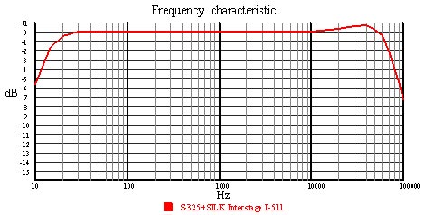
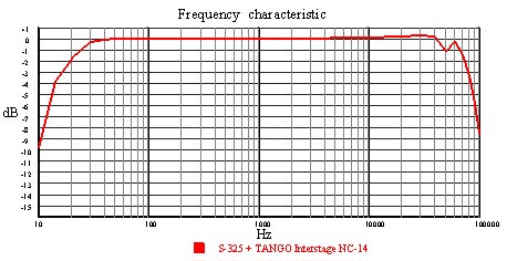
Frequency Response Frequency response is one of the most important aspects of Interstage transformer. Although some might argue that this has no benefit since human is limited in hearing up to only 20KHz, wide bandwidth output transformer usually means that it can generate true upper harmonic that bring music reproduction closer to the real life performance. These frequency response characteristics are done without shunting resistor. |
 |
||
| SILK I-511 Interstage transformer exhibits very wide bandwidth even under high DC unbalance current. -3.0dB point is from 15Hz to 75KHz with some tilt of around +0.5dB from 15KHz to 50KHz. This small amount of peak could be adjusted by secondary shunting of resistor value around 8,000 ohm. |
 |
||
| Same testing condition but using Tango NC-14 as Interstage transformer. As evident NC-14 also process wideband characteristic but has limited low frequency response than SILK I-511. NC-14 uses 10mm. cut core of Hi-B material that may be too small for handling very low frequency. |
|
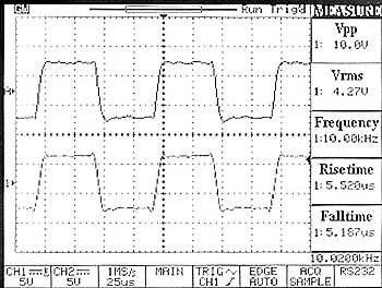
Square Wave behavior Good Interstage transformer must not only process wide bandwidth, but also generate uniform high frequency response that can be observed by assigning square waveform of some frequencies. The shape of square waveform will distort if non linear in high frequency response exist. Raise time, fall time and ringing time will indicate the "Signature" of each transformer. |
 |
||
| Above picture depicts two square waveforms of 10KHz at 10.0Vp-p level. Top waveform is from NC-14 and bottom waveform is from SILK I-511 Interstage transformer. Both waveforms display good square wave with very small ringing and minimum rise time and fall time. |
|
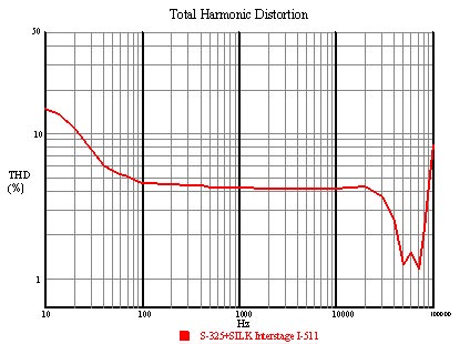
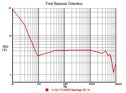
Total Harmonic Distortion (THD) THD is good measurement in performance of Interstage transformer. It will reveal the added distortion that Interstage transformer generates. In low frequency, high THD usually means that the core is saturate. |
|
||
| SILK I-511 has very low THD. At 10Hz to 50Hz THD figures are much less than NC-14 due to our generous core size, and precise air gap. Low THD translates into very tight, well define bass reproduction with dynamic and impact. |
|
||
| NC-14 has much higher THD in low frequency as expected from its lower inductance value than SILK I-511 |
|
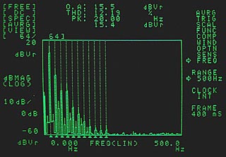
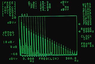
Fast Fourier Transform Analysis (Spectrum analysis) FFT analysis will enable see through distortion in frequency domain of each test signal that THD only able to give the total figure. Researchers suggested that the higher odd harmonic (5th, 7th, 9th and so on) usually has more perceptible effect than equivalent lower even harmonic (2nd and 4th ) thus THD figure of 0.1% which consists of 7th, 9th, 11th harmonic may sound worse than THD figure of 0.5% which consists of purely 2nd harmonic. |
|
|
|
|
FFT result for SILK I-511 shown 20Hz fundamental frequency. THD in this setup is 12.19% and its harmonics are mainly low order. |
|
FFT result for NC-14 reveals very severe distortion at 20Hz. THD figure is almost 50% and its harmonics could be seen up to 20th order! |